What is a Reliability Block Diagram (RBD)?
A Reliability Block Diagram (RBD) illustrates the status of a specific function in a system with several elements.
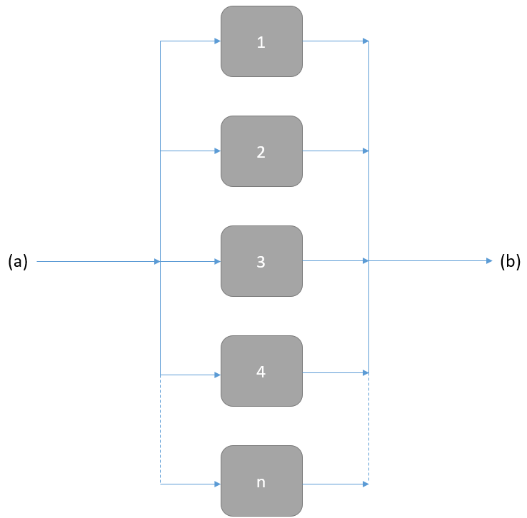
The diagram is made up of functional blocks that are represented as blocks and being connected by lines. The Reliability Block Diagram (RBD) has a single starting point (a) and a single ending point (b), as shown in the following figures:


Each function block can have two different states: a working state and a failed state. In addition, each block will have an associated failure rate.
A functional block can represent a component or a specific function of a component. When the specific function of the element will be available, we will illustrate it by saying that we can pass through the functional block. If we can pass through enough functional blocks to go from (a) to (b), then we will say that the system is operating with the main function specified.
Guidance for the construction and analysis of the RBD is provided in IEC61078 (2006). An RBD is not a physical design diagram, but a logical diagram illustrating what is required for the system to work. In an RBD, different blocks located at points in the diagram representing the same physical component can appear at various places in the diagram, if appropriate from a logical point of view.
An RBD illustrates the state of a specified system with several elements, constituting functional blocks and having a logical design. Such design is aimed at fulfilling a function that provides the necessary conditions to operate as specified. It can also be used to develop analytical formulas for calculating reliability and availability.
There is a special case of an RBD diagram which represents a voting system, i.e. by a redundancy structure, it is assumed that a certain number of elements (x of y) still work. This is the case, for instance, for a system 2 of 3 (2oo3, 2 out of 3). If two of the three devices lead to the same value, this is believed to be the correct value, since two of them are considered to be working correctly and the other one not.
One of the obvious but important starting points to take into consideration is that, for each functional block, we shall know its reliability. Therefore, the RBD will allow us to know the total reliability of the system, based on two basic pieces of information:
- The architecture of the elements which are part of our system.
- The very reliability of each of the components which compose our system.
In the case that we lack reliability of some of the elements, this normally means a lack of information of the element itself or that this element needs to develop a specific reliability block diagram (RBD) to find its equivalent reliability and to apply it to the global RBD of systems.
What is a Minimal Path Set?
These are the groups of elements in a system, for example: [equipment_1, equipment_3, equipment_4]; [equipment_1, equipment_5], that if each of them works (the equipment between [ ]), the system works correctly. Following the example, we would have two chains in parallel. The first consists of three pieces of equipment in series (1, 3 and 4) and two pieces of equipment in series (1 and 5). Only if one of the two branches work, the system will work properly.
What is a Minimal Cut Set?
It is the groups of elements in a system, for example [equipment_1, equipment_2], which ensures that when the group elements fail together, the system will fail. For example, in a pure serial system, we will have as many groups as elements, i.e. [team_1]; [team_2]; ... For example, in a pure serial system, we will have as many groups as elements, i.e. [team_1]; [team_2]; On the other hand, in a pure parallel system, all the equipment must fail at the same time, leaving a Minimal Cut Set structure of [equipment_1, equipment_2, ..., equipment_n].

What does a reliability analysis project with Railway RBD normally include?
Normally, a RAM Railway Analysis turnkey project uses as a normative basis the CENELEC EN50126, the IEC TR 62380 and the MIL-HDBK-338B standards. Its objective is generating a RAM report which provides qualitative and quantitative evidence that the system or installation designed meets the requirements of the project, involving among other activities to develop a system FMECA and an RBD. To carry out this development it will be necessary, among other things, to generate a product breakdown structure and perfectly define the application conditions influencing the System: restrictions imposed by existing infrastructure. For example, operating conditions, as well as operation and maintenance conditions, and strategies.
Our company Leedeo Engineering is a specialist in the development of Reliability Block Diagram (RBD) in our projects, giving support to our clients, at any level required for RAM and Safety tasks, and both at the level of infrastructure or on-board equipment.
Are you interested in our articles about RAMS engineering and Technology?
Sign up for our newsletter and we will keep you informed of the publication of new articles.


