RAMS analysis and Electromagnetic Compatibility (EMC)
Engineering based on RAMS analysis (" Reliability , Availability , Maintainability &
Safety": reliability, availability, maintainability and safety) is
one of the techniques that has been experiencing the greatest interest and boom
in recent years. Its use and implementation in the technical and quality
departments of the railway, avionics, automotive and nautical
sectors , allows the design and analysis of complex equipment or
systems in terms of safety and availability . The RAMS
analysis is carried out at the system level considering all the
components in a holistic way, so in RAMS can
converge mechanics, electricity, chemistry, electronics, software, firmware,
etc. In this way, RAMS engineering , with its analysis
and methodology, seeks to qualitatively and / or quantitatively analyze
and predict the capacity of a system, installation or
equipment to correctly perform its activity and its functions for which it has
been designed and manufactured. , at a technical, logistical and economic
level.
The challenge of RAMS engineering is to find the balance between the safety of the system and its availability to function since, as a general rule, both concepts are detrimental to each other. As a simplified example, we could say that, the more security, more maintenance and more maintenance, the less availability of the system. This means that a good RAMS analysis can have important economic implications for the viability of a product or system.
Thus, within the exercise of finding said balance, RAMS engineering analyzes the systems in a transversal way . And this includes the study of the electromagnetic compatibility (EMC) parameters of the system. RAMS engineers are increasingly aware of the need to study EMC in systems, so it is a topic of growing interest within the discipline.
The electromagnetic interference (EMI) are threats to the reliability, availability and safety of railway signaling systems, railways, airplanes and automobiles, not to mention sailing and electromedicine. Consequently, the identification of reliability, safety and availability requirements, which are dependent on environmental conditions, is a major issue for designers of electronic systems, and therefore for testers and testing and certification bodies . Reliability and safety requirements are established as a result of the electromagnetic (EM) environment , that is, radiated and conducted fields , which are a combination of all the EM threats surrounding an electronic system .
Therefore, on a recurring basis and with great relevance, Electromagnetic Compatibility Genetic, affects the reliability and safety requirements of a piece of equipment, system or installation.

Electronic equipment that can be critical from a RAMS point of view depends on the study of functional, thermal, mechanical and EMC aspects . Variation in any aspect could result in a breach of reliability, availability and security requirements . Traditionally, thermal or EMC issues were only considered after equipment or installation design was completed. Today this procedure is inadvisable.
The RAMS study promotes the application of methodologies to evaluate in advance, as far as possible, the effect that the malfunction of a subsystem or equipment may have on the complete system . For this, the analysis is based on the definition of threats , defining these as scenarios that can potentially lead to an accident . Likewise, a possible threat to consider for a system will most of the time be the Existence of EMC disturbances on the system / subsystem / equipment / installation .
The requirements and design parameters of each area and the relationship between them are defined qualitatively and / or quantitatively, depending on the project. Based on these dependencies between all areas, the cross-influence of each parameter variation on the requirements of other areas is demonstrated . The results obtained are intended to help meet the design requirements of any safety-critical equipment and to help designers know in advance the consequences of any design change, saving time and money. For the prevention of systematic failures , one must resort to the identification and application of corresponding EMC standards that prevent misdesign of the systems from an EMC point of view . However, for the study of random failures , a probabilistic analysis of the occurrence of such failures must be used. It is worth highlighting the importance of having identified these failures correctly and exhaustively. As an example, the application of this methodology in a safety communications radio on a railway is shown. This radio has the requirement to have a SIL 2 level related to its transmission functionalities, and the worsening of this requirement is exposed based on the EMC .
Once you have determined that EMC is important from a RAMS point of view , you must consider how to approach the problem. The first thing will be to analyze the failures in the system that can lead to the presence of EM disturbances . For this, from the RAMS point of view different strategies can be used, the most widespread (subjectively) being the performance of an FMECA study (" Failure Mode and Effect Critical Analysis ") ( AMFEC: "Analysis of Failure Modes , its Effects and Criticality "). Once these possible failures have been defined, an attempt should be made to ensure, as far as possible, that they do not occur. To do this, it must be borne in mind that there are two types of failure:
- A random failure is one that can be predicted by statistical probability.
- A systematic failure , on the other hand, will occur as long as certain conditions are met in the system.
For the study of EMC, both types of failure should be considered, since on the one hand a bad design can systematically cause the system to incur an EMC problem , but it is also possible that certain random failures trigger such a reaction.
THE SIL LEVEL
The level SIL ( " S afety I ntegrity L evel " : Integrity Level Security) is defined as the relative level of risk reduction provided by a safety function.
It is a measure of the security of a certain electronic
device or complete system. Within the same system we can find
different levels of security . The association of a
function to a certain SIL level is based on an analysis
called risk analysis . In the railroad industry, for
example, there are four SIL levels , each one
corresponding to a range of probability of occurrence , as
shown in figure 1, which indicates what are the allowed probabilities
of failure depending on the frequency of use of the functions. in
continuous mode. The probability of occurrence allowed
for a function that is used constantly is much lower than for another function
whose frequency of use is very low. Components with irregular use are
referred to as "low demand", and are dealt with in the IEC
61508 standard .
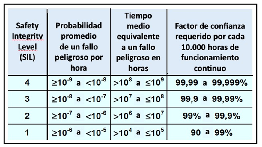
Figure 1: SIL safety levels. Probability of failure in continuous mode
The SIL concept is applied to different safety functions in the same complete system that includes electronics, electromechanics and mechanics. Generally, try to anticipate the ratios of incidence of EMI , it is inappropriate when it comes to achieving a certain level SIL . For example, even if a particular EMI happens once every ten years on average, the SIL level corresponds to the level of confidence that the safety function will withstand this EMI without failing, whenever it happens.
THE SYSTEMS
Signaling, communication and control systems are part of the critical safety systems included in various modes of transport, such as airplanes, ships, trains and automobiles. Generally, from a design perspective, there are three key areas to consider in the safety critical systems design process : functionality, temperature, and EMC . In critical reliability and safety systems , temperature and EMC requirements must be included . The three areas must be considered in parallel, moving in the same direction; considering the requirements multidisciplinary and its compliance in a controlled manner. The main objective is to establish a design methodology to define and quantify the relationship between RAMS design parameters and requirements with functional, thermal and EMC characteristics (figure 2).
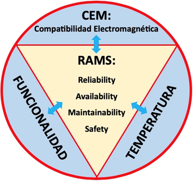
Figure 2: Relationships between RAMS characteristics, electromagnetic compatibility, functionality, and temperature
The functionality of an electronic system can be affected by EMC and by temperature. These parameters are identified in this article by the acronym FCT ( F uncionalidad, C EM, T emperature). The term FCT -> RAMS is related to the design parameters of the FCT areas and the analysis of RAMS requirements , while the term RAMS -> FCT is related to the design parameters of the RAMS requirements and the requirements analysis FCT .
DESIGN OF PARAMETERS AND REQUIREMENTS
The study of the failures of a system must entail taking containment measures so that they do not happen. These containment measures are passed on to the system in the form of requirements. In the event that certain failures are critical to the safety or availability of the system , it may be necessary to incur in the definition of reliability and safety requirements . Said requirements may refer (by way of example) to the demonstration that a certain piece of equipment has a probability of failure (failure rate) lower than a certain value, for example 10-5 failures / h.
To obtain the relationship between functional, thermal, EMC and RAMS parameters, it is first necessary to define the system requirements and design parameters of any equipment. The reliability requirement is the mean time to failure ( MTTF: "Mean Time To Failure " ). It is the arithmetic mean between failures of a system and is the time that the system is active, fulfilling the functionalities for which it has been designed.
The safety requirement is defined as the Tolerable Hazard Rate (THR ) . The two RAMS design parameters are the failure rate of the components and the use of safety improvement techniques, as defined for example by the EN 50129 standard (Adaptation of IEC 61508 to railway signaling electronics) . Two of these techniques are built -in self-test and redundancy . The self-test integrated is a process that allows a system to be tested if it to have high reliability and shorter repair cycle . The self-test integrated reduces the complexity of the configuration of the test, the signals reduce the amount of I / S to be examined. The self-test integrated adds an additional parameter for design: the average time of detection of the fault (MDT: "Mean Detection Time": average detection time) and should obviously data considered of reliability of the components of the topology added.
The parameters and functional requirements depend largely on the type of equipment designed. The design parameter that most affects reliability is the thermal architecture of the equipment. The requirements are the maximum and minimum ambient operating temperatures. EMC requirements are divided into immunity and emissions . Emission limits and immunity parameters are defined in the corresponding EMC standards . CEM design improvements consist of inserting components such as filters and other techniques such as good printed circuit design and wiring.
The RAMS analysis defines the relationship between the RAMS parameters and the discussed requirements. In most cases, the train safety radio transmitter or receiver consists of a main chain and it is assumed that a single failure causes a failure of the entire system. The MTTF reliability requirement is inversely proportional to this failure rate (failures / h).
ANALYSIS FCT -> RAMS and RAMS -> FCT
Remember the meaning of Acronym FCT ( Funcionalidad, CEM, Temperature). Once
all the requirements are defined, the first stage in system design is the definition
of the architecture to meet the functional requirements. The
functionality of the system can be achieved by different
architectures. The failure rate of the system depends on
the failure rate of each of its components. This information can be
obtained from the manufacturers or from the reliability databases in
the MIL-HDBK-217F standard , among others. These values provide
the information to determine if the computer meets the RAMS
requirements .
Thermal issues also affect the RAMS requirements of the system because, depending on the operating temperature of the components, their failure rate varies. The failure rate of a semiconductor component is exponentially dependent on the temperature of the silicon junction . Therefore it is necessary to use heat sinks properly.
One possible solution from an architectural point of view is to add redundancy . To meet EMC requirements , interference must be eliminated by adding additional components. Protections and filters against electrostatic discharge (ESD) and external surges are required on all external connectors in the system. Inserting these components worsens the MTTF system .
It is crucial to know that variations due to RAMS aspects affect the characteristics of the system with respect to FCT performance (RAMS -> FCT) . Changes aimed at improving security should not change the core functionality of the system, but the characteristics of the system blocks may vary if the new architecture requires them. There are two possibilities to improve system security: built -in self-test and redundancy . Both techniques affect the power and consumption of the RF signal transmitted by the radio.
The need to include components in the transmitter chain results in a reduction in transmitted power. Therefore, the characteristics of the equipment must be changed to obtain the same power output as in the absence of these improvements. The self-test integrated or redundancy involve insertion of new components in the system and, therefore, new signals. These signals can generate two types of EMC problems : EMI in the electromagnetic environment and EMI in system components ; both should be avoided.
RAMS ANALYSIS RESULTS
Once the causes and consequences between the FCT and RAMS characteristics have been analyzed , the results of the RAMS -> FCT and FCT -> RAMS analyzes are collected . Figure 3 shows FCT -> RAMS trends focused on EMC and functionality. In the case of integrated self-test technology, lowering the MDT (quantifiable parameter) improves THR , but, at the same time, the use of new (non-quantifiable) components worsens some requirements. The MTTF system is inversely proportional to the sum of the component failure rate . Therefore, the lower the failure rate of the integrated self-test components and the EMC, the less their effect on the MTTF system.
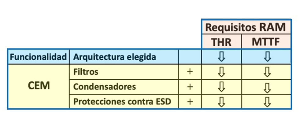
Figure 3: Effect of RAMS requirements. The columns
show the requirements and the rows define the design parameters. The trend
of the parameters is defined by the + symbol . The
"down arrow" symbol in the columns shows the worsening of the
requirement
Although these components generally have a very low failure rate, the failure rate of the components included in the system adds directly to the failure rate of the system. So, a trade-off must be considered between the failure rate of the used components and the MDT .
SAFETY COMMUNICATIONS RADIO
The methodology, based on the functional, thermal study of CEM and RAMS from the beginning, is applied to the design of an RF transmitter, with SIL 2 functionalities . As an example, let's look at a safety communications radio for a signaling system located on a high-speed train. RAMS requirements are defined by rail safety requirements . The minimum MTTF limit is defined as 5 x 10⁵ hours. While the transmitter security requirement is given by the THR related to the failure of security related functionality. This THR for the transmitter is 2.2 x 10⁻⁸ fault hours.
FCT -> RAMS analysis results
The basic architecture of the transmitter in the radio is based on a signal generator and different amplification stages. By means of the failure rate of each component at 25ºC and a confidence level of 60%, the calculation of the reliability data can be obtained . The proposed architecture (first line of figure 4) meets the MTTF requirement .
Environmental temperature conditions worsen the reliability data, as shown in the second line of the same figure 4. In addition, another effect that must be included in the RAMS calculations is the inclusion of components to mitigate EMI . The effect of these components is shown in the third line of figure 4, where the MTTF is 12.5% worse. Due to this reason, the integrated self-test is introduced (the hazard occurrence rate is 400 times per hour and the MDT used is 40 ms (fourth line of figure 4). Both requirements are met, although the MTTF slightly worse All values meet the requirement, but MTTF decreases with increasing temperature, built -in self test and EMC .
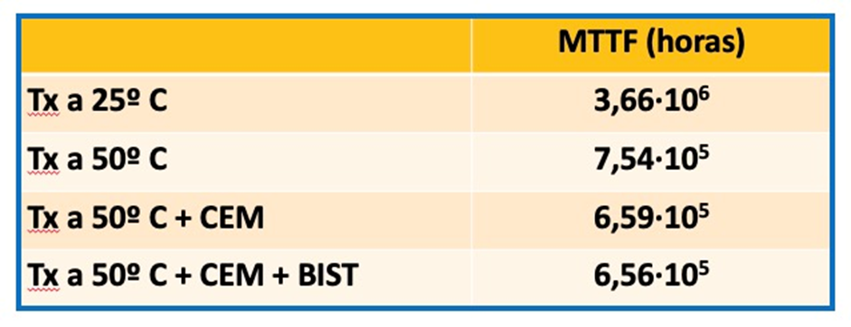
Figure 4: Reliability data (" realiability ") for four cases. Tx : Transmitter
RAMS Analysis Results -> FCT
From the point of view of the RAMS -> FCT analysis , the integrated self-test technique involves the insertion of a power detector, which generates a power loss. Therefore, it is necessary to increase the power output. Power consumption increases due to added components. The thermal characteristics of the included add-on components do not change significantly because the increase in power consumption is low. The last consequence of the integrated self-test technique is the variation of the EMC characteristics . The self-test is performed by digital systems, which can alter the operation of the transmitter. To avoid any malfunction, the necessary EMC filters must be included .
FUNCTIONAL SAFETY
The European Union safety directives regarding CE marking are "total safety" directives, which means that they cover all functional safety issues caused by EMI , but do not say how this should be achieved. The EMC directive and its standards or Automotive Regulation 10 do not cover safety issues and the IEC 61508 standard (basic IEC standard for functional safety in electrical / electronic systems) requires EMC to be taken into account , but does not say how it must be done. Figure 5 shows a relationship tree of the standards derived from the IEC 61508 standard . Therefore, it is important that the CEM community of experts reach out to the functional safety expert community and vice versa.
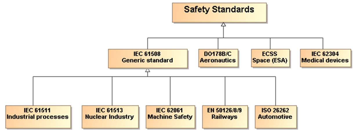
Figure 5: Safety regulations
The term functional safety is defined as: "Assurance
that the function of the system does not cause any intolerable state of
danger" , which implies that the system must be
fail-safe. Until now, the IEC 61508 standard has been the
only standard available for functional safety testing of a system. However,
the use of the IEC 61508 standard is not entirely without
problems. Some of the drawbacks when using it
are:
- The safety life cycle (sequence of phases that provide a logical path through commissioning, operation, maintenance and finally decommissioning) is designed for the process and automation industry.
- The design and testing of embedded systems is not covered very thoroughly in the IEC 61508 standard .
- Many of the electronic components in the industry are only available for a short time, which makes it difficult to find probabilistic data for a safety test before the start of production.
A security strategy must consider not only all elements within an individual system but also all security- related aspects of the systems that make up the functionality . All electronic technologies are inherently prone to inaccurate malfunction, malfunction, or even permanent damage when affected by EMI in their operating EM environments . Today's digital integrated circuits are decreasing their switching times and increasing their frequency bandwidth. Its level of integration makes it necessary to reduce the supply voltages, thus reducing the noise margin . Consequently, they have more emissions and more susceptibility . Manufacturers employing electronic devices in safety-critical systems have had few rules and regulations, and with many of them aiming for the lowest possible cost and meeting minimum regulatory requirements, functional safety issues are increasingly likely , such as shown in figure 6.
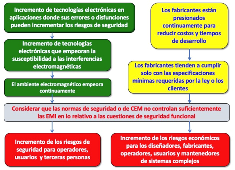
Figure 6: Increased risks in a complex system due to EMI
The IEC / TS 61000-1-2 standard is a
standard that covers EMC for functional safety ,
providing the EMC requirements that are missing from
the IEC 61508 standard . This standard uses
the hazard and risk- based assessment
approach. EMC testing is inappropriate when used as the
sole means of demonstrating that an acceptable level of EMC-related
functional safety performance has been
achieved .
Equipment EMC has traditionally been verified by testing usually a single sample of a new product. Equipment safety performance is traditionally verified by very different means:
- The design is inspected against a series of safety design criteria , tested to provide a sufficient level of protection over the intended life cycle, taking into account the physical environment (eg temperature and vibration) and reasonably foreseeable use.
- The samples are tested to see if a single foreseeable failure can result in a dangerous condition (" single failure safety ").
- Every piece of equipment that is manufactured undergoes basic tests that verify whether faulty parts or incorrect assembly have undermined the basic designed safety features.
Clearly, the traditional approach to the EMC test suite (domestic, commercial, industrial, automotive, rail, maritime, aerospace, medical, or military) is quite different from the approach taken by the safety approach. Immunity tests only cover one EM disturbance at a time. In real life and in normal operation, equipment is subjected to a series of EMIs simultaneously, for example: radiated fields from two or more transmitters transmitting simultaneously; a continuous radiating field plus a burst of fast transients or electrostatic discharges. The simultaneous RF interference can cause unexpected problems exotic EMI, to the Inter modular inside electronic devices.
EMC AND FUNCTIONAL SAFETY
The standards used as a framework for EMC testing only attempt to cover a typical EM environment and do not cover low probability EMI , which could affect the functional safety of the equipment or facility. Therefore, it is important to do an EMC risk analysis to find out what type of EMI the equipment could be exposed to. Also, there are no requirements to test the immunity of a vehicle when there are common electrical faults within it. These faults could be, for example, a short circuit in a filter, loose fasteners in a shield or a missing or deteriorated conductive gasket. Cable harnesses in vehicles, trains and facilities are systems that can function as EMI emitters or be sensitive to external disturbances. Whether an immunity test should be included in an EMC standard or a safety standard depends on the approval criteria. The test must be included in an EMC standard if it is required that during or after the test, the vehicle or equipment must continue to function as intended. If it is required that unsafe situations not occur (but performance may be incidentally or permanently degraded) during or after the test, the test should be included in a safety standard .
EMC IN THE SAFETY LIFE CYCLE
The framework of a safety standard that includes all safety activities from the conceptual phase to the dismantling of the equipment, vehicle or train is the safety life cycle . In the life cycle safety , the safety analysis is the basis for the specification of security requirements . Safety validation is done prior to commissioning. To achieve functional safety, EMC aspects must be considered throughout the life cycle of the equipment. Figure 7 shows a safety life cycle for a vehicle
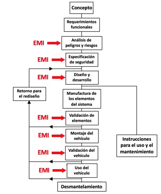
Figure 7: Security life cycle
The specific actions that must be taken in the
safety life cycle to achieve functional safety with
respect to EMI influences start with a definition of the
structure, design and intended functions of a piece of equipment. So it is
important to describe the relevant EM environment . There
are some phenomena MS that occur infrequently, not mentioned in
the rules, but should be considered in some cases. An example of such
phenomena are conducted or radiated disturbances in the frequency range below
150 kHz.
When describing the EM environment , safety must be specified in the requirements and also the failure criteria . First, the functional safety of a piece of equipment in the system itself will not be unduly affected by the EM environment in the place where the equipment is used. Second, any electromagnetic disturbance generated in a system will not unduly affect the functional safety of other parts of the system. It is important to perform a reliability analysis to identify hazards, which can cause safety risks due to EMI . Hazards must be identified in terms of events and the corresponding parts of the system. The methods for identifying hazards are generally based on two methods: bottom-up or top- down methodologies .
EMC tests for functional safety require special considerations regarding the selection of immunity test types and their test levels. When EMC testing is performed , the design can be modified to reduce the risks to acceptable values. The final design must be validated to demonstrate that the equipment works in accordance with the specified safety requirements.
ANALYSIS METHODS FOR EMC AND FUNCTIONAL SAFETY
To properly control EMC-related functional safety for equipment, hazard and risk assessments are needed . During this work, the following issues should be considered:
- What rare EM disturbances might the equipment be exposed to?
- What are the reasonably foreseeable effects of such EM disturbances on equipment?
- How could they issued the EMI by the team to affect the environment EM surrounding?
- What could be the reasonably foreseeable effects of the shocks mentioned above?
- What level of confidence or proof is required to demonstrate that the issues listed above have been fully considered and that all necessary steps have been taken to achieve the desired level of security?
ASCENDING METHODOLOGY
The bottom-up (or " Bottom- up") methodology of a reliability or safety study starts at the component level and shows the effect of failure of different individual components in the system. A common method that uses bottom-up methodology, FMEA (" Failure Mode and Effects Analysis ") or FMEA (" Modal Failure and Effects Analysis) is an analysis method that originally aimed to predict the reliability of systems. The purpose of the method is implemented requirements in the system for preventing the critical effects of the component failures or functions . the advantage of the method is that the analysis is very detailed component level and can be used to identify faults individual or the need of design changes, implementing redundant or failsafe technology.
An FMEA can be performed using a hardware approach or a functional approach . The hardware approach considers the failure mode of components in the hardware . The effects of EMI are usually the result of disturbances in the operating conditions (currents and voltages) of the components, rather than failures of the components themselves. Bottom-up methodology is not normally considered an appropriate approach to analyze the effects of EMIs .
The functional approach of an FMEA analysis is more appropriate for investigating the effects of EMI . With the functional approach, the method asks the question "In what ways can this function deviate from the specified requirement?" This approach identifies the most critical functions and will therefore require a higher level of immunity. From the bottom-up methodology, all failure modes are considered, including failure modes not relevant to EMI . It is an unnecessarily long and complicated method for complex systems.
DESCENDING METHODOLOGY
In a reliability study, the top-down (or "Top- down ") methodology is an event-oriented method , which allows the user to identify the levels and components of the team responsible for each specified top event. The user starts with a higher event at the highest level of interest and moves down to the level where the unwanted operation of the system occurs. The best known top-down method is fault tree analysis, which offers some advantages over EMC.
The FTA (" Fault Tree Analysis ": Fault Tree Analysis ) is a technique that allows to identify the combinations of faults that originate a certain event (called "top event "). Figure 8 shows an example of a fault tree.
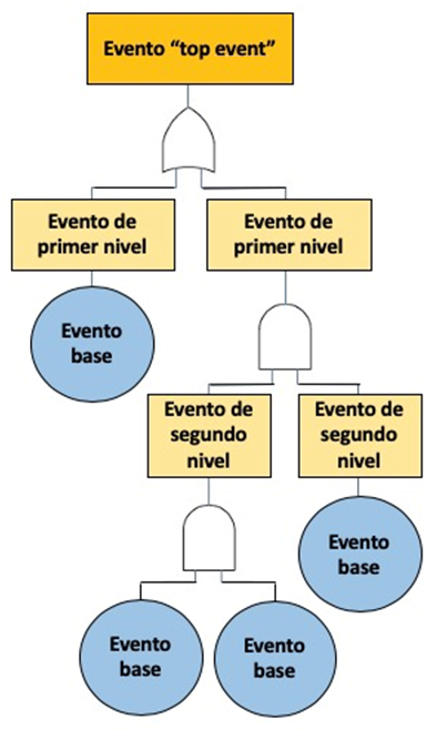
Figure 8: Example of fault tree
An FTA emanates from an unwanted event that is
investigated for possiblecauses . When possible causes are found
in a higher event, they are investigated. Finally, a logical
tree is built that starts at the system level and works down to
the root causes. Independent causes that interact in the fault tree are
expressed with " AND " gates and
alternative causes are expressed with " OR " gates . The
" OR " gates are the most critical parts
and should be taken care of first, as they correspond to the additional
probabilities of failure causes and therefore higher
risk . The strength of an FTA analysis is that it is a
structured search for the causes of a specific event with the purpose of
eliminating security threats.
Below the first-level events are the second-level events, which are the events that could cause the first-level event. The analysis continues with several levels until the base events are found . In the case of using the FTA method to analyze the circuit from an EMC point of view, the EMIs are considered base events . For a large system like a train, the fault trees are often many, large, and complex. Therefore, it is important to limit the FTA to the main critical security events .
There are some advantages to using FTA analysis to evaluate EMF . The method can handle both common cause failures and time varying failure rates , which is important when analyzing behavior during the presence of EMI in equipment. Another benefit is that events in an FTA scan are not limited to just failures, but can also involve performance degradation or other factors external to the system.
At Leedeo Engineering , we are specialists in the development of Railway RAMS, Electromagnetic Compatibility and CENELEC regulations, supporting RAM and Safety tasks at any level required, and both at the infrastructure or on-board equipment level.
Are you interested in our articles about RAMS engineering and Technology?
Sign up for our newsletter and we will keep you informed of the publication of new articles.


